This project simulates a variable duty cycle PWM signal generator with verilog. It generates a PWM signal of 10MHz, it has a button to increase the duty cycle by 10% and one to decrease the duty cycle by 10%. The verilog code has been taken from fpga4student.com
A Pulse width modulated signal generator is used widely in the industry in many applications. PWM generator produces a square wave with a fixed time period but a variable duty cycle. Because the PWM can operate at high frequencies, it finds applications as a voltage controller in many devices.
PWM generator is used in many applications like:
- DC/DC and DC/AC cconverters
- Inverters
- Controlling brightness of lights
- Controlling loudness in speakers
- Controlling speed of motor


Install the following tools with commands given (for linux):
- Verilog
- GTKwave
- Yosys
$   sudo apt-get update
$   sudo apt-get install iverilog gtkwave
$   sudo apt-get install -y yosys
Use the following commands to clone the github repo and run the files:
$   sudo apt install -y git
$   git clone https://github.com/pranav1751/iiitb_pwm
$   cd iiitb_pwm
$   iverilog iiitb_pwm_gen.v iiitb_pwm_gen_tb.v
$   ./a.out
$   gtkwave pwm.vcd
The simulation results when increasing duty cycle
 The simulation results when decreasing duty cycle

Note: in the yosys_run.sh file, change the path name for the lib file as it is in your directory
# read design
# read_liberty -lib /media/psf/Home/Stark/Education/ASIC/iiitb_pwm_gen/lib/sky130_fd_sc_hd__tt_025C_1v80.lib
read_verilog iiitb_pwm_gen.v

# generic synthesis
synth -top iiitb_pwm_gen

# mapping to mycells.lib

dfflibmap -liberty /home/imt2020544/iiitb_pwm/lib/sky130_fd_sc_hd__tt_025C_1v80.lib
abc -liberty /home/imt2020544/iiitb_pwm/lib/sky130_fd_sc_hd__tt_025C_1v80.lib -script +strash;scorr;ifraig;retime,{D};strash;dch,-f;map,-M,1,{D}
clean
flatten
# write synthesized design
write_verilog -noattr iiitb_pwm_synth.v
# stat
# show
Use the following commands to generate the Gate Level Simulation file from the initial iiitb_pwm_gen.v
$ iverilog -DFUNCTIONAL -DUNIT_DELAY=#1 primitives.v sky130_fd_sc_hd.v iiitb_pwm_gen_synth.v iiitb_pwm_gen_tb.v
$ ./a.out
$ gtkwave pwm.vcd
note: I extracted the files primitives.v sky130_fd_sc_hd.v out of the verilog_model folder and kept them in the main folder as there was an error accessing them inside the folder for some unknown reason.
OpenLane is an automated RTL to GDSII flow based on several components including OpenROAD, Yosys, Magic, Netgen, CVC, SPEF-Extractor, KLayout and a number of custom scripts for design exploration and optimization. The flow performs all ASIC implementation steps from RTL all the way down to GDSII.
Read more and installation guide at https://github.com/The-OpenROAD-Project/OpenLane\
Installation
Prerequisites:
- docker installation guide: https://docs.docker.com/get-docker/
Magic is a venerable VLSI layout tool, written in the 1980's at Berkeley by John Ousterhout, now famous primarily for writing the scripting interpreter language Tcl. Due largely in part to its liberal Berkeley open-source license, magic has remained popular with universities and small companies. The open-source license has allowed VLSI engineers with a bent toward programming to implement clever ideas and help magic stay abreast of fabrication technology. However, it is the well thought-out core algorithms which lend to magic the greatest part of its popularity. Magic is widely cited as being the easiest tool to use for circuit layout, even for people who ultimately rely on commercial tools for their product design flow.\ More about magic and installation guide at http://opencircuitdesign.com/magic/index.html
run the following commands on the terminal:
$   cd OpenLane/
$   cd designs/
$   mkdir iiitb_pwm_gen
$   cd iiitb_pwm_gen/
$   wget https://raw.githubusercontent.com/pranav1751/iiitb_pwm_gen/main/config.json
$   mkdir src
$   cd src/
$   wget https://raw.githubusercontent.com/pranav1751/iiitb_pwm_gen/main/iiitb_pwm_gen.v
$   cd ../../../
$   sudo make mount
$   ./flow.tcl -design iiitb_pwm_gen!
Screenshot from 2022-09-11 18-22-37
The layout files for the run are created in iiitb_pwm_gen/runs. Find the most recent run, it has all the files, and the def physical layout files.\ Using magic to view the .def files.
- Go to the folder where the final def file is located, here it is, /home/ubuntu/OpenLane/designs/iiitb_pwm/runs/RUN_2022.09.11_12.50.55/results/final/def
- Run the command
magic -T /home/ubuntu/OpenLane/pdks/sky130A/libs.tech/magic/sky130A.tech lef read ../../../tmp/merged.nom.lef def read iiitb_pwm_gen.def &
The following window appears, showing the layout

Lets include in library and in the final layout. Clone the vsdcelldesign repo in Openlane/ using the following command
$ git clone https://github.com/nickson-jose/vsdstdcelldesign
copy sky130A.tech to vsdstdcelldesign directory
Viewing the vsdinv cell
'''
$ magic -T sky130A.tech sky130_inv.mag
'''
 in tkcon terminal using the following, generate the lef file
% lef write sky130_vsdinv
 Copy the generated lef file to designs/iiit_pwm_gen/src. Also copy lib files from vsdcelldesign/libs to designs/iiit_pwm_gen/src. /
Open the OpenLane directory and run the following commands:
Copy the generated lef file to designs/iiit_pwm_gen/src. Also copy lib files from vsdcelldesign/libs to designs/iiit_pwm_gen/src. /
Open the OpenLane directory and run the following commands:
$ sudo make mount
$ ./flow.tcl -interactive
% package require openlane 0.9
% prep -design iiitb_pwm_gen
% set lefs [glob $::env(DESIGN_DIR)/src/*.lef]
% add_lefs -src $lefs

% run_synthesis
% run_floorplan
% run_placement
% run_cts
% run_routing
Pre synthesis stats

Post synthesis stats

To view the layout in magic, go to results/routing in your runs folder and enter the following command:
magic -T /home/ubuntu/OpenLane/pdks/sky130A/libs.tech/magic/sky130A.tech lef read ../../tmp/merged.nom.lef def read iiitb_pwm_gen.def &
Note: Change the directories for your PC.

% getcell sky130_vsdinv

This shows that vsdinv cell is included.


OpenSTA is a gate level static timing verifier. As a stand-alone executable it can be used to verify the timing of a design using standard file formats.
OpenSTA uses a TCL command interpreter to read the design, specify timing constraints and print timing reports. Read more at OpenSTA Github
After opening openlane, enter sta to open it.
Place the following files in the pdks/sky130A directory (from runs/results/ctc)

Run the following commands:
%	read_liberty -min /home/ubuntu/OpenLane/pdks/sky130A/libs.ref/sky130_fd_sc_hd/lib/sky130_fd_sc_hd__ff_n40C_1v56.lib
%	read_liberty -max /home/ubuntu/OpenLane/pdks/sky130A/libs.ref/sky130_fd_sc_hd/lib/sky130_fd_sc_hd__ff_n40C_1v56.lib
%	read_verilog /home/ubuntu/OpenLane/pdks/sky130A/iiitb_pwm_gen.v
%	link_design iiitb_pwm_gen
%	read_sdc /home/ubuntu/OpenLane/pdks/sky130A/iiitb_pwm_gen.sdc
%	set_propagated_clock [all_clocks]
%	report_checks

%	report_checks -from _247_ -to _244_
%	report_checks -from  _247_ -to _245_

Post Synthesis gate count = 177

Area = 9064.8 micron^2

Performance = 272.47 MHz

Flipflop/Standard cell ratio = 40/177 = 0.2259

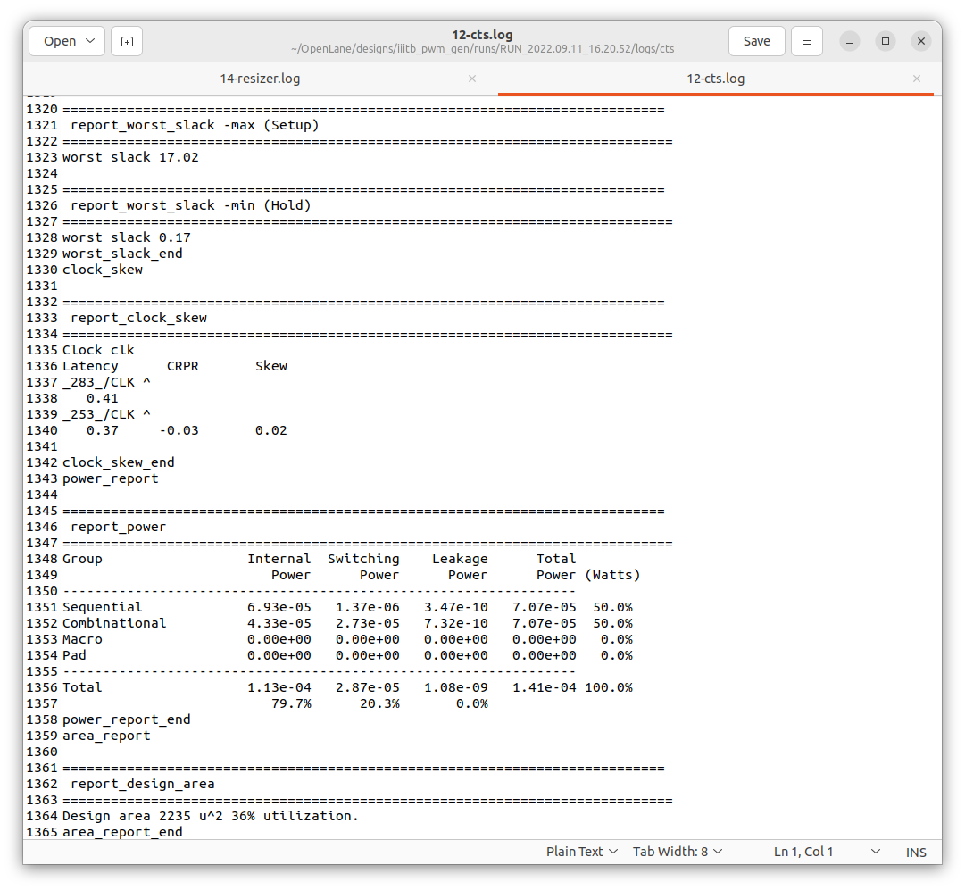
Power consumed = 0.141mW

-
Pranav Vajreshwari, iMtech2020 IIITB
-
Kunal Ghosh, Director, VSD Corp. Pvt. Ltd.
- Kunal Ghosh, Director, VSD Corp. Pvt. Ltd.
-
Pranav Vajreshwari, Pranav.Vajreshwari@iitb.ac.in
-
Kunal Ghosh, Director, VSD Corp. Pvt. Ltd. kunalghosh@gmail.com