This repository contains design of a traffic light controlling module made using verlilog and simulation of the same.
Traffic lights are signaling devices used to manage traffic using different colours of light(Red, Green and Yellow). Usually we have two traffic light connected by same module working in sync. They are placed on cross-roads to avoid accidents and to maintain proper movement on roads. This model can be implemented using a microcontroller, programmable gate array or application specific IC.
Traffic lights are commonly used in
- places which are more crowded and have high risk of accidents
- places like schools and hospitals
- sometimes traffic lights are used to signal danger like places which are surrounded by fog
The block diagram of traffic light controller is shown below:
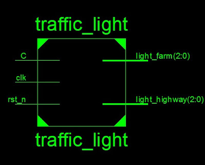
The design has five main parameters to it.
The C button here is a sensor response, which will activate once any disturbance occurs on the area it is directed.
The clock will keep track of time which can be used to decide the time to change the traffic signal.
The reset button is used for initialisation of the whole process. As the whole system is autonomous, reset button won't be needed after first step.
And then there are light_farm and light_highway parameters which will output the respective signals on two traffic light connected by sensor.
Icarus Verilog is a Verilog simulation and synthesis tool. It operates as a compiler, compiling source code written in Verilog (IEEE-1364) into some target format. For batch simulation, the compiler can generate an intermediate form called vvp assembly. This intermediate form is executed by the vvp command.
GTKWave is a fully featured GTK+ based wave viewer for Unix and Win32 which reads LXT, LXT2, VZT, FST, and GHW files as well as standard Verilog VCD/EVCD files and allows their viewing. We will be using this tool to simulate the output of our main code using a testbench.
This is a framework for RTL synthesis tools. It currently has extensive Verilog-2005 support and provides a basic set of synthesis algorithms for various application domains.
-
For Ubuntu/ Linux mint:
Open the terminal and enter the following commands$ sudo apt-get update $ sudo apt-get install iverilog $ sudo apt-get install gtkwave $ sudo apt-get install yosys -
For arch based distros:
Open the terminal and enter the following commands$ sudo pacman -Syu $ sudo pacman -S iverilog $ sudo pacman -S gtkwave $ sudo pacman -S yosys
First, make sure to have git package installed in your device. Then proceed with following commands:
$   sudo apt install -y git
$   git clone https://github.com/m4ury4p/IIITB_ASIC_traffic_controller

$   cd IIITB_ASIC_traffic_controller/

$   iverilog iiitb_traffic_light_controller.v iiitb_traffic_light_controller_tb.v
$   ./a.out

$   gtkwave pre_synthesis.vcd
I would recommend setting the interval of 10 microseconds and "zoom to fit" to see waveforms properly.
In computer engineering, logic synthesis is a process by which an abstract specification of desired circuit behavior, typically at register transfer level (RTL), is turned into a design implementation in terms of logic gates, typically by a computer program called a synthesis tool.
Common examples of this process include synthesis of designs specified in hardware description languages, including VHDL and Verilog.Some synthesis tools generate bitstreams for programmable logic devices such as PALs or FPGAs, while others target the creation of ASICs. Logic synthesis is one aspect of electronic design automation.
Yosys can be adapted to perform any synthesis job by combining the existing passes (algorithms) using synthesis scripts and adding additional passes as needed by extending the yosys C++ code base.
Here, we will use following commands to run our script.
$   yosys
$   read_liberty -lib /lib/sky130_fd_sc_hd__tt_025C_1v80.lib
$   read_verilog iiitb_tlc.v
$   synth -top iiitb_tlc
$   abc -liberty /home/iiitb_tlc/lib/sky130_fd_sc_hd__tt_025C_1v80.lib
$   write_verilog -noattr iiitb_tlc_synth.v
$   stat
$   show
The term "gate level" refers to the netlist view of a circuit, usually produced by logic synthesis. So while RTL simulation is pre-synthesis, GLS is post-synthesis. The netlist view is a complete connection list consisting of gates and IP models with full functional and timing behavior.
RTL simulation is a zero delay environment and events generally occur on the active clock edge. GLS can be zero delay also, but is more often used in unit delay or full timing mode. Events may be triggered by the clock, but will propagate according to the delays on each element.
The loading and wiring delay models of the netlist can be estimated by the synthesis tools, or can be output from the layout tools. These delay models usually come in the form of an SDF (standard delay format) file.
To run Gate Level Simulation, run commands given below:
$   iverilog -DFUNCTIONAL -DUNIT_DELAY=#1 verilog_model/primitives.v verilog_model/sky130_fd_sc_hd.v iiitb_tlc_synth.v iiitb_tlc_tb.v
$   ./a.out
$   gtkwave post_synthesis.vcd
As we can see here , our pre and post synthesis outputs are same.


OpenLane is an automated RTL to GDSII flow based on several components including OpenROAD, Yosys, Magic, Netgen, CVC, SPEF-Extractor, CU-GR, Klayout and a number of custom scripts for design exploration and optimization. The flow performs full ASIC implementation steps from RTL all the way down to GDSII.
To install and test the tool, we can run following commands and tests:
 $git clone https://github.com/The-OpenROAD-Project/OpenLane.git

 $ cd OpenLane/

 $ sudo make

 $ sudo make test
Magic is an electronic design automation (EDA) layout tool for very-large-scale integration (VLSI) integrated circuit (IC) originally written by John Ousterhout and his graduate students at UC Berkeley.
Magic features real-time design rule checking, something that some costly commercial VLSI design software packages don't feature. Magic implements this by counting distance using Manhattan distance rather than Euclidean distance, which is much faster to compute.
To install this tool,we need to install some packages listed below:
$   sudo apt-get install m4
$   sudo apt-get install tcsh
$   sudo apt-get install csh
$   sudo apt-get install libx11-dev
$   sudo apt-get install tcl-dev tk-dev
$   sudo apt-get install libcairo2-dev
$   sudo apt-get install mesa-common-dev libglu1-mesa-dev
$   sudo apt-get install libncurses-dev
Then, we install magic tool:
$ git clone https://github.com/RTimothyEdwards/magic
$ cd magic/
$ ./configure
$ sudo make
$ sudo make install
Then we can type magic in terminal to verify if our installation was successful or not.
To create custom inverter cell, follow these intructions:
$ git clone https://github.com/nickson-jose/vsdstdcelldesign.git
$ cd vsdstdcelldesign
$  cp ./libs/sky130A.tech sky130A.tech
$ magic -T sky130A.tech sky130_inv.mag &
The output will look like this:

Then we can type the following commands in the tcl console to extract the spice netlist:
% extract all
% ext2spice cthresh 0 rthresh 0
% ext2spice
The changes will occur in sky130_inv.spice file in your vsdstdcelldesign directory

Then, open the extracted spice netlist and edit its contents as following:

After changing the file, use the following commands in currernt directory:
$ ngspice sky130_inv.spice
It will start ngspice in terminal and show the parameters and their values in the file. Then type following command:
-> plot y vs time a
It will show the output as given below:

Then, we can us select show grids option in our magic tool's menu bar or use grid in tcl console to review the placement of ports.

To save the file:
% save sky130_vsdinv.mag
make sure to use different name for our .mag file.
Then run the new .mag file and generate the .lef file using commands given below:
$ magic -T sky130A.tech sky130_vsdinv.mag
//In tcl console
%lef write
To simulate the layout, we will follow the steps shown below:
$ cd /OpenLane/designs
$ mkdir iiitb_tlc
$ touch config.json
$ cd iiitb_tlc
$ mv $HOME/iiitb_tlc/config.json OpenLane/designs/iiitb_tlc/config.json
Then, copy the src directory from home/iiitb_tlc and paste it in openlane/designs/iiitb_tlc.
After that, run the following commands:
$ cd OpenLane
$ sudo systemctl start docker
$ sudo make mount
$ ./flow.tcl -interactive
It will open the container in openlane directory.
Then, type the following in terminal:
% package require openlane 0.9

% prep -design iiitb_tlc

% lefs [glob $::env(DESIGN_DIR)/src/*.lef]
% add_lefs -src $lefs
Now, open the mergerd.nom.lef file in /$run_directory/tmp and it should have the definition of sky130_vsdinv:

% run_synthesis
After typing above command, synthesis will start running. After the completion of two steps, we will get something like this in reports/synthesis directory:


Now, our netlist should include sky130_vsdinv after synthesis:

% run_floorplan
After, typing above command, we will get our floorplanning results:
First, the die area:


Now, open terminal in results/floorplan directory and type the following command in new terminal:
magic -T /home/garudamp/OpenLane/pdks/sky130A/libs.tech/magic/sky130A.tech lef read ../../tmp/merged.nom.lef def read iiitb_tlc.def &
change garudamp by your home directory's name.
Now, we will get the floorplan view in our magic tool as below:


% run_placement
After running this code, we will get our gate placement report.
Navigate to results/placement directory and open the terminal.Then type this:
magic -T /home/garudamp/OpenLane/pdks/sky130A/libs.tech/magic/sky130A.tech lef read ../../tmp/merged.nom.lef def read iiitb_tlc.def &
It will give us the following result:

We can also locate the sky130_vsdinv in this view:

In our updated netlist we can find the sky130_vsdinv

% run_cts
The cts report will look like following:


% run_routing
Navigate to results/routing directory and open the terminal.Then type this:
magic -T /home/garudamp/OpenLane/pdks/sky130A/libs.tech/magic/sky130A.tech lef read ../../tmp/merged.nom.lef def read iiitb_tlc.def &
It will look like this:
 The vsdinv in the routing view.


Gate Count = 262

Area = 72612.133 (um)^2


Performance = 1 / (clock period - slack) = 1/(50 - 38.47) = 0.0867 MHz

Flip Ratio = No. of flipflops / No. of Cells = (59 + 2) / 262 = 0.233

Internal power = 89.5 uW (65.1%) Switching Power = 48.0 uW (34.9%) Leakage Power = 20.8 nW (0%) Total Power = 137 uW (100%)
- Maurya Patel
- Kunal Ghosh, Director, VSD Corp. Pvt. Ltd.
- Maurya Patel, Integrated MTech ECE Student, International Institute of Information Technology, Bangalore Maurya.Patel@iiitb.ac.in
- Kunal Ghosh, Director, VSD Corp. Pvt. Ltd. kunalghosh@gmail.com
- https://www.fpga4student.com/2016/11/verilog-code-for-traffic-light-system.html
- https://www.academia.edu/21200096/DESIGN_AND_IMPLEMENTATION_OF_TRAFFIC_LIGHTS_CONTROLLER_USING_FPGA_A_Project_Based_Laboratory_Report_in_partial_fulfilment_for_the_award_of_III_IV_B_Tech_I_Semester_Submitted_by_Lab_Instructor
- https://iverilog.fandom.com/wiki/GTKWave
- https://en.wikipedia.org/wiki/Logic_synthesis